Hot Keywords:
- All
- Product Name
- Product Keyword
- Product Model
- Product Summary
- Product Description
- Multi Field Search
Views: 4 Author: Site Editor Publish Time: 2025-02-20 Origin: Site
Cross pin is an important component of the universal axis of locomotive internal combustion engine. Cross pin fracture will bring some safety risks to railway traffic. A locomotive cross-pin broke. The cross-pin material is high-quality 20CrMnTi alloy steel, and the heat treatment process is carburizing and quenching treatment. The researchers used a series of physical and chemical tests to analyze the causes of the fracture to prevent such problems from happening again.
1 Physical and chemical tests
1.1 Macro-scale observation
The broken cross pin is cleaned by ultrasound, and the macroscopic morphology of the fracture is shown in Figure 1. After visual inspection, there are two main crack sources and two secondary crack sources (see area A in Figure 1), and there are fatigue strips distributed on the section. There are multiple inconsistent cracks at the chamfer of the cross pin, which extend from the chamfer platform to the chamfer arc transition zone (see Figure 2). According to the preliminary judgment: the cross pin in the use of bending alternating stress. Under the action of bending alternating stress, the two main cracks expand from both sides to the middle (see area b in Figure 1). Further observation shows that the main crack source area in the upper part of Figure 1 is relatively clear, and the main crack expansion rate in the upper part is faster than that in the lower part; the two secondary cracks do not leave a clear crack expansion path due to less force. The c area in Figure 1 is the transient fracture area. According to the preliminary judgment of the crack extension path, the fracture source of the cross-pin appears in the chamfer site, and the fracture mode is multi-source fatigue fracture.
1.2 Chemical composition analysis
The chemical composition analysis of the cross specimens was performed using a direct reading spectrometer and the results are shown in Table 1. According to Table 1, its chemical composition meets the requirements of GB / T 3077- -2015, Alloy Structural Steel.
1.3 Metallographic test
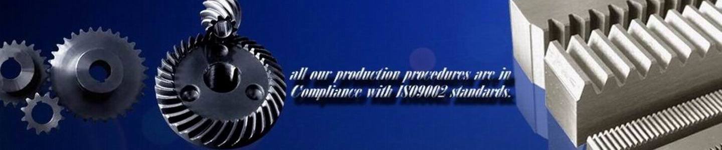
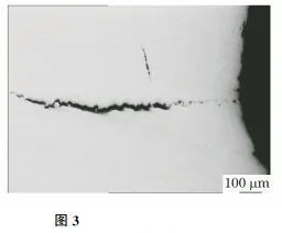
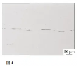
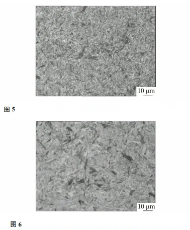
The gold phase sample was taken at the fracture site and placed under an optical microscope for observation, showing a zigzag crack with a depth of about 1.05mm in the chamfer area of the cross pin, and more large size and strip MnS mixed on the surface of the sample (see Figure 3~4). After using the volume fraction of 4% nitrate ethanol solution, the depth of the surface carburization layer was about 1.46mm. The surface tissue of the sample was in order: tempering martensite + a small amount of flextensite (depth 0.45mm) (see Figure 5), quenched martensite + a small amount of flextensite (depth 0.55 mm) (see Figure 6), and bessite + martensite (depth 0.55mm) (see Figure 7). The matrix tissue is martensite + besite + ferrite (see Figure 8).
1.4 Hardness test
The hardness test of the cross section of the pin sample shows that the Rockwell hardness of the noncarburized layer is relatively uniform, and its value is 28.1~31.2HRC. All the cross section and the matrix tissue was quite homogeneous.
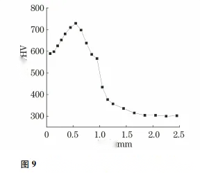
The hardness test was performed on the metallographic specimens, and the results are shown in Figure 9. As can be seen from Figure 9, the hardness of the sample from shallow to deep increases first and then decreases, reaching the maximum value at 0.55mm from the surface, at 729 HV, and then the hardness gradually decreases and tends to stabilize. The change in hardness corresponds to changes in the microorganization of the surface layer, and the poor quenching of martensitic organization in the surface layer may result from inadequate tempering.
1.5 Scanning electron microscope (SEM) analysis
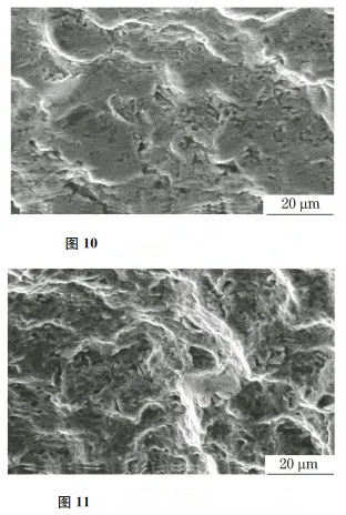
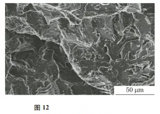
The SEM morphology of the crack source area of the cross-pin fracture is shown in Figure 10. It can be seen from Figure 10: in the crack source area, there are more uneven fatigue strip small plane or small pits, and the small plane is smooth. With the expansion of the fatigue cracks, the strip spacing becomes smaller, and the injustice degree of the strips and small pits intensifies (see Figure 11). Figure 12 shows the SEM morphology of the cross pin instantaneous break area, with the morphology characteristics of the break, and the cross pin breaks quickly as a whole.
From the macroscopic morphology, the multi-source fatigue fracture. The cross-pin is mainly subject to the effect of bending and alternating stress during use. Under the action of alternating stress, the chamfer site bears the largest load, and the material cracks at the interface between the sulfide and the matrix, forming a microcrack source. Martensite quenching in the carburizing layer of the cross pin
2 Comprehensive analysis
With large strength and hardness, large stress in the tissue and gap sensitivity, the bad tissue may be caused by insufficient tempering after quenching. Therefore, the major cause of cross-pin fracture is the presence of relatively large size MnS inclusions in the interior and the presence of poorly quenched martensitic tissue in the surface layer. The small amount of strain generated by the chamfer site will form the hole between the large size MnS inclusion near the chamfer and the steel matrix. Under the stress, the hardened martenite organization on the surface accelerates the formation of microcrack source. In the crack expansion stage, the spacing of the fatigue strip is small and the strip is uneven, which indicates that the crack expansion rate is slow; when the crack expands to a certain size, the material bearing area shrinks and cannot withstand the stress, leading to the rapid expansion of the crack, resulting in the overall fracture of the cross pin.
3. Conclusion and suggestions
The fracture form of the cross pin is multi-source fatigue fracture. The quenching martensitic tissue in the surface layer and the large size and strip MnS inclusions in the material create the conditions for the formation of micro crack source, which forms cracks in the weak organization of the material. It is suggested to improve the cleanliness of molten steel and improve the heat treatment process to reduce large size inclusions in steel and avoid bad microtissue.