Hot Keywords:
- All
- Product Name
- Product Keyword
- Product Model
- Product Summary
- Product Description
- Multi Field Search
Views: 4 Author: Site Editor Publish Time: 2025-01-06 Origin: Site
1. Characteristics of the gear gap elimination design
(1) Improve the transmission accuracy: in the precision transmission system, such as CNC machine tools, precision instruments, etc., the tooth side clearance will lead to the transmission error. After eliminating the gap, the movement of the active wheel can be accurately transmitted to the driven wheel, which avoids the position deviation caused by the gap, and improves the positioning accuracy and repeated positioning accuracy of the whole system.
(2) Enhance stability and reduce noise: the clearance will cause the gear to produce impact and vibration in the engagement process, resulting in the increase of noise. The gap can make the gear engagement more tightly and smoothly, reduce the impact, reduce the operating noise, and improve the stability and comfort of the equipment operation. For example, in the gear transmission of vehicle transmission and power tools.
(3) prolong the gear life: reasonable gap elimination can make the gear load distribution more uniform. When there is a gap, the gear engagement moment is prone to local stress concentration and accelerate wear. After the gap, the stress concentration is reduced and the gear wear is more uniform, thus extending the service life and reducing the equipment maintenance cost.
(4) Improve the response speed of the system: in the system with high response speed requirements, such as the servo system, the gap will cause the lag of movement transmission. After eliminating the gap, the system can respond to the control signal more quickly and accurately, improve the dynamic performance of the system, and ensure the timeliness and accuracy of the control.
2. The principle of gear gap elimination
(1) Adjust the center distance to eliminate the gap: eliminate the gap by changing the center distance to the gear pair. For standard mounted gear, the center distance can reduce or even eliminate the tooth side clearance of the gear. This is based on the engagement characteristics of the involute gear affecting the size of the tooth side gap.
(2) Wrong tooth clearance: make one gear into two pieces, make the two gears rotate at an Angle in a certain way, and closely fit with the two sides of another gear, so as to eliminate the tooth side clearance. For example, the double piece of thin gear wrong tooth adjustment structure, the use of spring force or other external force to make the two pieces of thin gear produce relative rotation, to achieve the wrong tooth clearance.
(3) Flexible adjustment of gap elimination: using the elastic deformation of elastic elements (such as spring, rubber, etc.) to compensate for the gap of the gear. When the gear rotates in different directions, the elastic element can always maintain the force on the gear, keeping the gear close together and eliminating the gap.
3. Design of gear gap elimination
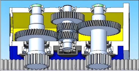
1. Design of double-chip thin gear error-tooth adjustment method
(1) Structural design: replace a wide gear with two thin gears, and install a spring or other elastic elements between the two thin gears, so that they produce the trend of relative wrong teeth. The spring force should be designed reasonably according to the number of module, teeth, load and other parameters of the gear to ensure sufficient air gap force.
(2) Adjustment mode: it can be changed by adjusting the length and tension of the pulling spring. Spring tension: in the adjustment structure of double thin gear, the tension is generally determined according to the modulus of gear. For gears with modulus m=2-5, the pull of a single pull spring is usually in the range of 5-20N. For example, for gears with analog m=3, a single pull spring tension can be set to 8N if the load is small; if the load is large, the tension can be adjusted to about 15N.
(3) Amount of wrong teeth; adjustable eccentric sleeve can also be used to adjust the relative position of two thin gears to achieve clearance. The amount of wrong teeth is related to the gap. Generally, the amount of wrong teeth should be slightly greater than the space of the teeth. Assuming a tooth side clearance of 0.1mm, for gears with modulus m=4, the amount of misteeth may be set between (0.12-0.15mm by calculation and actual adjustment. Eccentricity- -In an adjustable eccentric sleeve structure, the amount of eccentric sleeve is generally between 0.05-0.2mm. For the transmission system with moderate precision requirements, the analog m=3 gear, offset sleeve offset can be selected 0.1mm. By adjusting the Angle of the eccentric sleeve, the relative position of the double thin gear can be adjusted to eliminate the gap.
2. Axial insert adjustment method design
Gasket thickness calculation: accurately calculate the thickness of the gasket according to the gear modulus, number of teeth, tooth side clearance requirements and other parameters. The thickness of the spacer should ensure that it can effectively eliminate the tooth side gap without making the gear produce too large axial force. The gasket thickness is calculated according to the tooth side clearance. For example, for the standard mounted gear pair with modulus m=5 and tooth number z=30, if it is required to eliminate the tooth side clearance of 0.15mm, the thickness of the spacer is about 0.18-0.2mm (considering the assembly error and elastic deformation of the material).
Material selection: the gasket material should have a certain elasticity and wear resistance, such as copper alloy, rubber, etc., to adapt to the axial displacement of the gear and long-term friction. If copper alloy gasket is used, its elastic modulus is about 100-120 GPa; if rubber gasket is used, its elastic modulus is within 0.01-1 GPa, the specific value depends on the type and hardness of rubber.
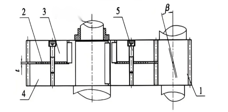
3. Double-guide worm gap elimination design
Cochlear design: the left and right sides of the worm are different, and the engagement gap of the worm wheel is adjusted by changing the axial position of the worm. The guide difference of worm should be designed according to the modulus, tooth number and clearance requirements of worm wheel.
Lead difference: The lead difference of the two-guide worm is usually between 0.1-0.5mm. For the worm worm with module m=2, if the fine gap adjustment is required, the guide difference can be designed to be 0.2mm.
Adjustment mechanism: design accurate axial adjustment mechanism, such as adjusting nut, screw, etc., so as to accurately adjust the axial position of the worm and achieve accurate adjustment of clearance.
Axial adjustment: determine the axial adjustment of the worm according to the guide difference and the transmission ratio of the worm wheel. For example, if the transmission ratio i=40 and the guide difference is 0.3mm, the worm moves 1mm per axis, and the angle change of the worm wheel can change the tooth side clearance by about 0.0075mm (0.340). In the actual adjustment, to eliminate the gap of 0.1mm, the axial adjustment amount of the worm is about 1.33mm.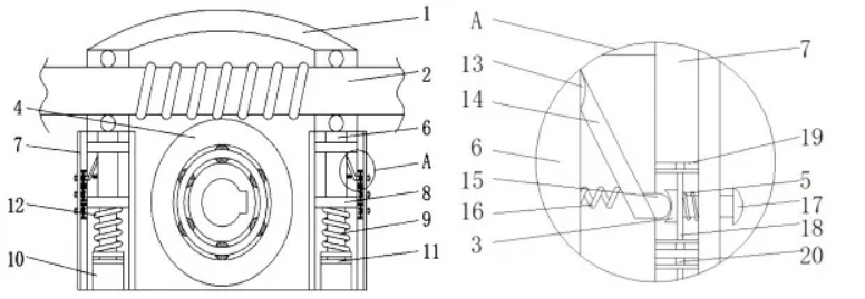
4. Major experience of gear gap elimination
1. Application scenario data of different gap elimination methods
Double-piece thin gear wrong tooth adjustment method: suitable for small load, high transmission accuracy requirements. Usually in the module of 1-6mm, speed in 100-3000 r/min gear transmission system is widely used. For example, in small precision instruments (such as the focusing mechanism of optical microscope), the gear module is generally 1-2mm, and the speed is not more than 500 r/min. The two-piece thin gear error adjustment method can effectively eliminate the clearance and ensure the accuracy of focusing.
Axial gasket adjustment method: often used for medium load, speed in 50-2000 r/min gear transmission. For the modulus in 3-8mm, this method can achieve the gap. For example, in the feeding system of ordinary machine tools, the modulus is 4-6mm and the speed is 200-1000 r/min, the tooth side clearance can be controlled within the range of 0.05-0.15mm through the axial gasket adjustment method to meet the requirements of machining accuracy.
Double guide worm gap elimination: mainly used for worm worm transmission, transmission accuracy and self-locking performance requirements are high. Generally applicable to module 2-10mm, worm head number 1-4, transmission ratio between 10-100. For example, in the rotary table drive mechanism of some automatic production lines, the modulus is 5mm, the number of worm heads is 2, the transmission ratio is 30, and the worm gap can be controlled between 0.03-0.1mm.
2. Experience data of assembly and debugging
(1) Double-chip thin gear wrong tooth adjustment method:
Spring preload force: According to the gear modulus and load, 5-15N when the modulus is small and the load is light, the preload force can be increased to 15-30N. For example, light load gear of 3mm, each spring preload can be set to 8N; modulus of 5mm midload gear, each spring preload is set to 20N.
Adjustment of the wrong tooth amount: usually the amount of the wrong teeth is 1.2-1.5 times of the tooth side gap. If the tooth gap is 0.1mm, the wrong tooth is adjusted to 0.12-0.15mm.
(2) Axial insert adjustment method:
Gasket thickness tolerance: Gasket thickness tolerance should be controlled within ± 0.02mm to ensure the stability of the backgap effect. For example, the calculated spacer thickness is 0.2mm, and the actual processed thickness of the spacer should be between 0.18-0.22mm.
Axial force during assembly: in the assembly process, the applied axial force should not be too large, generally controlled within the range of 50-150N, to avoid gear deformation or aggravated wear caused by excessive axial force.
(3) Double-guide worm clearance:
Axial adjustment accuracy of the worm: the axial adjustment accuracy of the worm should reach less than ± 0.05mm to achieve accurate gap elimination. For example, in order to eliminate the gap of 0.08mm, the axial adjustment amount of the worm is 1mm, and the actual adjustment accuracy should be guaranteed between 0.95-1.05mm.
Contact spot: after assembly, the contact spots of the worm wheel shall account for 60% -80% of the width of the tooth surface and be evenly distributed to ensure good engagement performance.
3. For the gear transmission system working in high temperature environment, consider the influence of thermal expansion on the clearance, and reserve appropriate clearance compensation.