Hot Keywords:
- All
- Product Name
- Product Keyword
- Product Model
- Product Summary
- Product Description
- Multi Field Search
Views: 2 Author: Site Editor Publish Time: 2024-12-12 Origin: Site
I. Definition and Structure
A spline is a connection structure in mechanical transmission. It consists of an external spline on the shaft and an internal spline on parts such as the hub. The external spline usually has multiple key teeth machined on the surface of the shaft, shaped like a flower. The internal spline has keyways machined on the hole wall of the hub to match the external spline. Its function is to transmit torque and ensure the concentricity between the shaft and the hub, enabling them to maintain a good coaxial relationship during rotation.
II. Classification
Classification by tooth profile:
(1) Rectangular spline: Its tooth profile is rectangular. The rectangular spline has the characteristics of high centering accuracy and relatively strong load-bearing capacity. Its processing technology is relatively simple and the cost is low, so it is widely used in general mechanical transmission. For example, in the gearbox of machine tools, it is used to connect gears and shafts to realize the functions of power transmission and speed change.
(2) Involute spline: The tooth profile is in the shape of an involute. The advantage of the involute spline is its good automatic centering performance. Due to the characteristics of the involute, during the assembly process, the tooth surfaces can automatically adjust their positions to ensure concentricity. Moreover, its tooth root is relatively thick and its strength is high, so it is suitable for transmitting larger torques and higher rotational speeds. For example, the connection between the half shaft and the hub of a car often adopts the involute spline to withstand the complex loads during the vehicle's driving process.
(3) Triangular spline: Its tooth profile is triangular. This kind of spline has the characteristic of high centering accuracy, but its load-bearing capacity is relatively weak. It is mainly used in connection occasions with light loads and high precision, such as the connection between shafts and parts in some precision instruments. (From left to right in sequence: rectangular spline, involute spline, triangular spline) 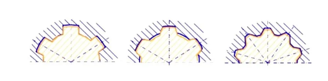
III. Characteristics of Spline Couplings
Spline couplings are suitable for connections with high requirements for centering accuracy, large loads or frequent sliding. The number of teeth, dimensions, fits, etc. of spline couplings should all be selected according to standards.
(1) Since a relatively large number of teeth and grooves are directly and evenly made on the shaft and the hub hole, the forces on the connection are relatively evenly distributed.
(2) Because the grooves are relatively shallow, the stress concentration at the tooth root is relatively small, and the strength reduction of the shaft and the hub is less.
(3) There are more teeth and the total contact area is relatively large, so it can bear relatively large loads.
(4) The alignment between the parts on the shaft and the shaft is good (which is very important for high-speed and precision machines).
(5) The guiding performance is relatively good (which is very important for dynamic connections).
(6) The machining accuracy and connection quality can be improved by grinding methods.
(7) The disadvantages of spline couplings are that there is still stress concentration at the tooth root; sometimes special equipment is required for processing; and the cost is high. 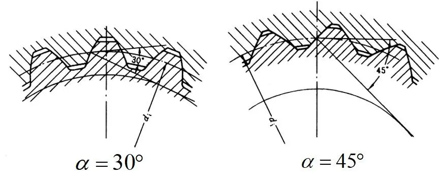
IV. Design of Spline Couplings
1. Determine the Type of Spline Rectangular spline: It has high centering accuracy and strong load-bearing capacity. The rectangular spline has two series, namely the light series and the medium series. The light series is often used for static connections with lighter loads, such as the connection between the sliding gear and the shaft in a gearbox. The medium series is suitable for connections with medium loads. Involute spline: It has the characteristic of automatic centering, and its tooth root is relatively thick with high strength. It is often used for connections with large loads and high requirements for centering accuracy, such as the connection between the automotive half shaft and the hub. Its standard pressure angles include three types: 30°, 37.5° and 45°. The involute spline with a 30° pressure angle has a higher load-bearing capacity. Four basic tooth profiles are specified for the two types of tooth roots, namely the flat tooth root with a 30° pressure angle, the rounded tooth root with a 30° pressure angle, the rounded tooth root with a 37.5° pressure angle, and the rounded tooth root with a 45° pressure angle. Triangular spline: It has good centering performance and can automatically center to ensure the coaxiality of the shaft and the hub and reduce vibration and noise. It is suitable for precision transmission, such as the connection between the spindle of a precision machine tool and the gear. It has relatively strong load-bearing capacity and can bear loads through multiple teeth. With reasonable design, it can bear considerable loads. It is often used in places with light to medium loads and limited space, such as the connection between the gears and the shaft in a small car transmission. Its structure is compact. Under the same conditions, it occupies less space than the rectangular spline, which is beneficial for miniaturization design, such as the connection between handheld electric tools, micro motors and reducers.
2. Determine the Basic Parameters of the Spline
(1) Rectangular spline Firstly, determine the basic parameters such as the minor diameter d, the major diameter D, the key width B and the number of teeth z. The minor diameter d is the main dimension and is initially selected according to the diameter of the shaft and the transmitted torque. The key width B and the number of teeth z are determined according to the load-bearing capacity and structural requirements. The number of teeth z is generally an even number for the convenience of processing and inspection.
(2) Involute spline Determine the basic parameters such as the module m, the number of teeth z and the pressure angle (generally 30° or 45°). The module is an important parameter of the involute spline, which determines the size and load-bearing capacity of the spline. The larger the module, the larger the tooth thickness and tooth height of the spline, and the stronger the load-bearing capacity. The minor diameter is the main dimensional parameter of the rectangular spline and is determined according to the strength of the shaft and the connection requirements. For example, in some automotive transmission systems, the module m may be between 2 - 3mm. The number of teeth z also needs to consider the load-bearing capacity and structure, and generally is not less than 10. The involute spline with a 30° pressure angle has a stronger load-bearing capacity, and the involute spline with a 45° pressure angle is more suitable for occasions with light loads and small sizes.
(3) Basic parameters Determine the basic parameters such as the module m, the number of teeth z and the pressure angle (generally 30° or 45°). The choice of the number of teeth z depends on the diameter of the shaft, the requirements for the transmitted torque and the overall structural layout of the equipment. Generally speaking, shafts with smaller diameters will adopt relatively fewer teeth, while for shafts with larger diameters and higher transmitted torques, the number of teeth will increase accordingly to ensure sufficient load-bearing capacity and uniform load distribution. The module m is a key parameter that determines the size and load-bearing capacity of the triangular spline. The larger the module, the larger the size of the teeth, and correspondingly the higher the load-bearing capacity of the spline. The size of the pressure angle α directly affects the shape of the tooth profile and the stress characteristics. The tooth profile of the triangular spline with a 30° pressure angle is relatively "gentle". When transmitting larger torques, the contact stress distribution on the tooth surface is relatively uniform, which is beneficial to improving the load-bearing capacity and wear resistance of the tooth surface and is suitable for occasions with large loads and relatively stable operation. While the tooth profile of the triangular spline with a 45° pressure angle is relatively "steep". Its advantage is that under the same conditions of module and number of teeth, the thickness at the tooth root is relatively large and can bear relatively large bending stresses. Therefore, it is often used in some transmission systems with relatively large load changes and possible impact loads. However, relatively speaking, the contact stress distribution on its tooth surface is not as uniform as that of the 30° pressure angle, and the tooth surface wear may be relatively fast when working under high loads for a long time.
3. Strength Calculation The main failure modes of spline couplings are crushing of the working surface (for static connections) or excessive wear of the working surface (for dynamic connections). For static connections, strength calculation is carried out according to the extrusion stress on the working surface, and for dynamic connections, conditional strength calculation is carried out according to the pressure on the working surface.
(1) Checking of Rectangular Splines
① Calculation of Tooth Surface Contact Strength:
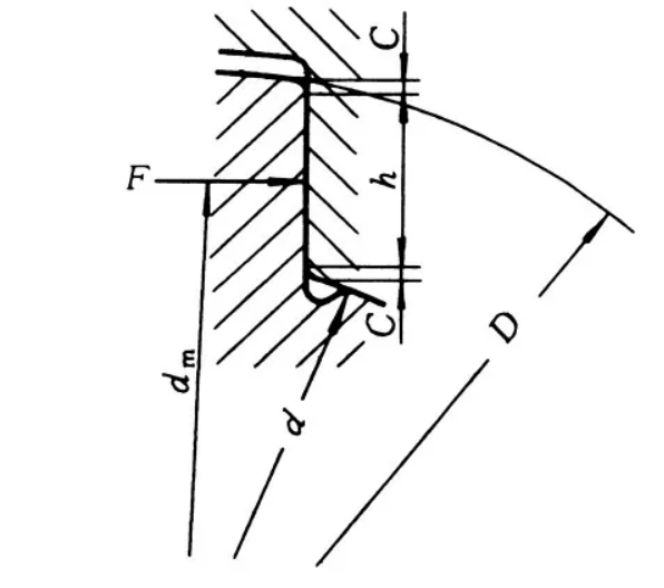
When the rectangular spline transmits torque T, the calculation formula for the tooth surface contact stress σH is σH = 2T / (ψzhlDm). Here, ψ is the uneven coefficient of load distribution (generally taken as 0.7 - 0.8), h is the working height of the key tooth (for the rectangular spline, h = [(D - d) / 2] - 2C, where C is the chamfer size), l is the working length of the spline, and Dm = (D + d) / 2.
After calculating the contact stress σH, it should be less than the allowable contact stress [σH]. The value of the allowable contact stress is determined according to the spline material and working conditions (such as whether there is lubrication, working temperature, etc.). For example, for 45 steel after quenching and tempering treatment, under good lubrication conditions, the allowable contact stress [σH] may be between 100 - 150 MPa.
② Calculation of Tooth Root Bending Strength:
The tooth root bending stress σF = 2T / (zblDm), where b is the tooth root width (for the rectangular spline, b = B - 2C).
The calculated tooth root bending stress σF should be less than the allowable bending stress [σF]. The allowable bending stress is related to the mechanical properties of the material and the heat treatment state of the spline. For example, for 40Cr steel after quenching and tempering, the allowable bending stress [σF] may be around 150 - 200 MPa.
③ Checking of Centering Accuracy:
For rectangular splines, if the minor diameter is used for centering, the dimensional accuracy and cylindricity of the minor diameter need to be checked. The dimensional tolerance grade of the minor diameter should be selected according to the centering accuracy requirements of the connection. For example, for precision transmission, the dimensional tolerance grade of the minor diameter can be selected as IT6 - IT7; for general transmission, IT8 - IT9 can be selected. The cylindricity error should be controlled within the allowable range to ensure the centering accuracy.
(2) Checking of Involute Splines
① Calculation of Tooth Surface Contact Strength:
When the involute spline transmits torque T, the calculation formula for the tooth surface contact stress σH is σH = ZE[(2T / (ψzm²l)) · 1 / (1 / ρ1 + 1 / ρ2)]¹/². Here, ZE is the elastic coefficient (related to the material), ρ1 and ρ2 are the radii of curvature at the contact points of the two tooth surfaces, ψ is the uneven coefficient of load distribution (the value range is similar to that of the rectangular spline), and l is the working length of the spline.
The calculated σH should be less than the allowable contact stress [σH]. The allowable contact stress is determined according to the spline material and working conditions. For example, for involute splines made of high-quality alloy steel, under good lubrication and normal working temperature conditions, the allowable contact stress [σH] may be between 200 - 300 MPa.
② Calculation of Tooth Root Bending Strength:
The tooth root bending stress σF = 2T YFKF / (zm²l), where YF is the tooth form factor and KF is the load factor (considering factors such as dynamic loads).
The calculated σF should be less than the allowable bending stress [σF]. The allowable bending stress is related to the strength of the material and its heat treatment state. For example, for alloy steel after carburizing and quenching treatment, the allowable bending stress [σF] may be around 250 - 350 MPa.
③ Checking of Centering Accuracy:
The involute spline is centered by the tooth form. The accuracy of the tooth form needs to be checked, including tooth form errors, cumulative pitch errors, etc. The tooth form accuracy grade is selected according to the centering accuracy requirements of the connection. For example, for the involute spline connection in high-precision aerospace equipment, the tooth form accuracy grade may be required to reach grade 5 - 6; for general industrial equipment, grade 7 - 8 can meet the requirements.
(3) Checking of Triangular Splines
① Calculation of Tooth Surface Contact Strength:
The formula for calculating the tooth surface contact stress σH is σH = 2T / (ψzhlDm). Here, T is the transmitted torque, ψ is the uneven coefficient of load distribution (usually taken between 0.7 - 0.85, specifically depending on factors such as the machining accuracy, assembly quality and working conditions of the spline), h is the working height of the tooth (for the triangular spline, h = m(1 + cosα), where m is the module and α is the pressure angle), l is the working length of the spline, and Dm = (d + D) / 2 (d is the minor diameter of the spline and D is the major diameter of the spline).
Compare the calculated tooth surface contact stress σH with the allowable contact stress [σH]. The value of the allowable contact stress depends on the material, heat treatment method and lubrication conditions of the spline. For example, for 45 steel after quenching and tempering treatment, under good lubrication conditions, the allowable contact stress [σH] is approximately between 120 - 180 MPa; if alloy steel is used and appropriate surface hardening treatment is carried out, the allowable contact stress can be increased to 200 - 300 MPa or even higher.
② Calculation of Tooth Root Bending Strength:
The calculation formula for the tooth root bending stress σF is σF = 2T / (zblDm), where b is the tooth root width (for the triangular spline, b = mπsinα).
The calculated tooth root bending stress σF needs to be less than the allowable bending stress [σF]. The allowable bending stress is closely related to the strength, toughness and hardness after heat treatment of the material. For example, for 40Cr steel after quenching and tempering, the allowable bending stress [σF] may be in the range of 180 - 250 MPa; while for alloy steel after carburizing and quenching treatment, the allowable bending stress can reach around 250 - 350 MPa.
③ Checking of Centering Accuracy:
Centering Method: The triangular spline adopts the tooth form centering method. During the machining and assembly process, centering is achieved by the precise meshing of the internal and external spline tooth forms. This centering method can ensure high centering accuracy, and during the working process, even when subjected to certain load fluctuations or impacts, due to the mutual restraint of the tooth forms, it can still maintain the coaxiality between the shaft and the hub well.
Accuracy Requirements: In order to ensure good centering effect and transmission performance, strict requirements are imposed on the tooth form accuracy, pitch accuracy and surface roughness of the triangular spline. The tooth form accuracy is usually controlled according to the tolerance grades specified in relevant standards. For example, in precision transmission, the tooth form tolerance grade may be required to reach IT6 - IT7; the cumulative pitch tolerance also needs to be controlled within a small range to ensure the uniform distribution of each tooth on the circumference and avoid the load concentration phenomenon caused by pitch deviation. In terms of surface roughness, the roughness value of the tooth surface is generally required to be between Ra0.8 - Ra3.2 μm. A lower surface roughness helps to reduce the friction and wear of the tooth surface and improve the transmission efficiency and service life of the spline. During the machining process, precision milling, broaching or grinding processes are often used to ensure these accuracy requirements. Meanwhile, before assembly, strict inspection of the spline is required to ensure that all accuracy indicators meet the design requirements.
4. Tolerance and Fit Design
According to the usage requirements and working conditions of the spline, select appropriate tolerance grades and fit types. For connections with high accuracy requirements, such as the connection between the spindle of a machine tool and the cutting tool, higher tolerance grades need to be selected to ensure the accuracy and stability of the connection. Fit types include clearance fit, transition fit and interference fit. Clearance fit is used for dynamic connections to facilitate the relative sliding of the spline; interference fit is used for static connections and can transmit larger torques; transition fit is between the two.
5. Design of Spline Length
The length of the spline is mainly determined according to the magnitude of the torque that needs to be transmitted by the connection. On the premise of ensuring the transmission of sufficient torque, try to shorten the length of the spline as much as possible to reduce manufacturing errors and costs. Meanwhile, if the length of the spline is too long, it will lead to increased machining difficulty and may result in uneven stress during the working process.
6. Material Selection
Carbon Steel: Such as 45 steel, it has good comprehensive mechanical properties and a relatively low price. After appropriate heat treatment (such as quenching and tempering treatment), it can be used for triangular splines with general loads and medium accuracy requirements. It is widely used in some mechanical equipment that is relatively cost-sensitive and has less harsh working conditions.
Alloy Steel: For example, 40Cr, 20CrMnTi, etc. Alloy steel has higher strength, toughness and wear resistance. Through appropriate heat treatment processes (such as quenching and tempering, carburizing and quenching, etc.), it can significantly improve the load-bearing capacity and service life of the spline. It is suitable for occasions where large loads need to be borne, high-speed operation or the working environment is relatively harsh (such as high temperature, high humidity, the presence of corrosive media, etc.), such as key transmission parts in automobile engines, aero engines and industrial robots.
During the spline design process, issues such as machining processes, lubrication and sealing also need to be considered to ensure the reliability and service life of the spline connection.