Hot Keywords:
- All
- Product Name
- Product Keyword
- Product Model
- Product Summary
- Product Description
- Multi Field Search
Views: 3 Author: Site Editor Publish Time: 2025-05-30 Origin: Site
Surface roughness is very important for most surfaces involved in sliding contact because factors such as the original rate of wear and the nature of the duration are highly dependent on this characteristic. These surfaces are generally load-bearing and need to be marked roughness to ensure suitability for the intended use.
Many parts need to have a specific surface finish in order to achieve the desired function. For example, the body of a car before painting or the neck bearing on a crankshaft or camshaft.

What is surface roughness?
Surface roughness (Surface Roughness) is what we call surface roughness in our daily measurements, which can be understood as the unevenness of small spacing and tiny peaks and valleys in the process of processing products.
It is usually defined as the small distance between two wave peaks or two wave troughs (wave distance). In general, wave distance is within 1mm or less. It can also be defined as the measurement of micro contour, commonly known as micro error value.
To sum up, you may have a general idea of roughness, so the following is a more detailed analysis.
We generally evaluate the roughness with a baseline, the highest point above the baseline is called the wave peak point, and the lowest point below the baseline is called the wave trough point, so the height between the wave peak and the wave trough is represented by Z, and the spacing of the micro texture of the processed product is represented by S.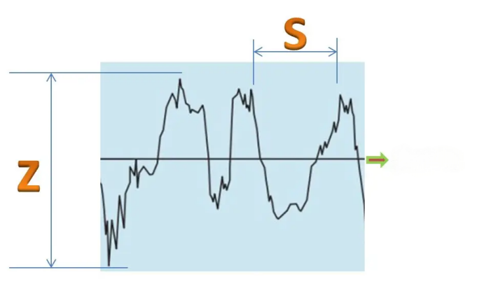
In general, the size of S value is defined in the national verification standard:
S <1mm is defined as surface roughness 1≤S≤10mm is defined as surface ripple
According to China's national metrological verification standard, VDA3400, Ra and Rmax are usually used to evaluate the verification surface roughness, and the unit is usually expressed by μm.
The relationship between evaluation parameters
Ra is defined as the average arithmetic deviation of the curve (average roughness), Rz is defined as the average height of the unevenness, and Ry is defined as the maximum height. The maximum height difference of the micro contour, Ry, is also expressed by Rmax in other standards.
Please refer to the following table for the specific relationship between Ra and Rmax: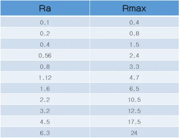
Table: Comparison of Ra and Rmax parameters (um)
How is surface roughness formed?
The formation of surface roughness is caused by the machining process of the workpiece. The machining method, the material of the workpiece and the process are all factors that affect the surface roughness.
For example, discharge machining is used to produce discharge bumps on the surface of the workpiece.
The processing technology and part material are different, and the micro traces left on the surface of the processed part are also different (density, depth, shape change, etc.).
Effect of surface roughness on workpiece
The wear resistance of the workpiece, the stability of the fit, the fatigue strength, the corrosion resistance, the sealing, the contact stiffness, the measurement accuracy... The coating, the thermal conductivity and contact resistance, the reflection ability and radiation performance, the resistance to the flow of liquids and gases, the current flow on the surface of the conductor, etc., will have different degrees of influence.
Evaluation basis of surface roughness
① Sampling length
The unit length of each parameter and the sampling length are the length of a baseline used to evaluate surface roughness. Under ISO1997 standards, 0.08mm,0.25mm,0.8mm,2.5mm is generally used and 8mm is the baseline length.
② Evaluate length
It is composed of N reference lengths. The surface roughness of each part of the component surface cannot truly reflect the true parameter of the roughness on a reference length, but it is necessary to take N sampling lengths to evaluate the surface roughness. The evaluation length under ISO1997 standard is generally N equal to 5.
③ base line
The baseline is the contour median used to evaluate roughness parameters. Generally, there are two types: the least squares median and the arithmetic mean contour median. [Least Squares Median] involves calculating the points collected during measurement using the least squares method. [Arithmetic Mean Contour Median] ensures that the areas of the upper and lower parts of the contour on the median are equal within the sampling length.
In theory, the least squares median is the ideal baseline, but it is difficult to obtain in practical applications, so the arithmetic median of the contour is generally used instead, and a position approximate straight line can be used for substitution during measurement.