Hot Keywords:
- All
- Product Name
- Product Keyword
- Product Model
- Product Summary
- Product Description
- Multi Field Search
Views: 1 Author: Site Editor Publish Time: 2024-12-30 Origin: Site
1. baseline
Parts are composed of several surfaces, between each surface has a certain size and mutual position requirements. The relative position requirements between the surfaces of the parts include two aspects: the distance between the surfaces, the dimensional accuracy and the relative position accuracy (such as axion, parallel, verticality and circular beating, etc.) requirements. The relative position relationship between the surface of the parts is inseparable from the reference, and the position of the surface of the parts cannot be determined without the clear reference. In its general sense, the reference is the point, line and surface used on the parts to determine the position of other points, lines and surfaces. According to their different functions, the benchmark can be divided into two categories: design benchmark and process benchmark.
1. Design benchmark
In the part diagram to determine the other points, lines, surface of the reference, called the design reference, for the piston, the design reference refers to the piston center line and pin hole center line.
2. Technology benchmark
The reference used in the machining and assembly process of the part is called the process reference. Process datum is divided into positioning benchmark, measurement benchmark and assembly reference according to different uses.
① Positioning reference: the reference used to make the workpiece in the correct position in the machine tool or fixture, called the positioning reference. According to the different positioning components, the most commonly used have the following two categories: automatic centering positioning: such as three claw dial positioning. Positioning sleeve positioning: the positioning element into a positioning sleeve, such as the stop plate positioning of other positioning in the V frame, positioning in the semicircular hole positioning, etc.
② Measurement datum: the datum used to measure the size and position of the processed surface, called the measurement datum.
③ Assembly reference: the base used to determine the position of a part in a component or product, called the assembly reference.
2. Installation method of the workpiece
In order to process a surface that meets the specified technical requirements on a certain part of the workpiece, it is necessary to make the workpiece occupy the correct position on the machine tool relative to the tool before machining. This process is often called the "positioning" of the artifacts. After the positioning of the workpiece, due to the effect of cutting force and gravity in the processing, certain mechanisms should also be used to "clamp" the workpiece, so that the determined position remains unchanged. The process of keeping the workpiece in the right position on the machine tool and tightening the workpiece is called "installation". The quality of workpiece installation is an important problem in mechanical processing, which not only directly affects the processing accuracy, the speed and stability of workpiece installation, but also affects the level of productivity. In order to ensure the relative position accuracy between the machining surface and its design reference, the design reference of the machining surface should occupy a correct position relative to the machine tool when installing the workpiece. For example, in the fine car ring groove process, in order to ensure the requirements of the bottom diameter of the ring groove and the skirt axis, the workpiece must make the design reference coincide with the shaft spindle of the machine tool. When process parts on a variety of different machine tools. The installation method can be summarized into three kinds: direct alignment method, marking alignment method and clamp installation method.
1, directly to the correct method
In this method, the correct position that the workpiece should occupy on the machine tool is obtained through a series of attempts. The specific way is to install the workpiece directly on the machine tool, with the percentage table or the spot on the needle plate, to correct the correct position of the workpiece, while checking, until it meets the requirements
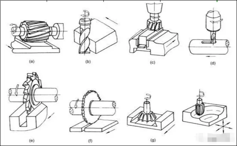
Main motion: directly remove the cutting layer on the workpiece and transform it into chips, thus forming the motion of the new surface of the workpiece, called the main motion. During cutting, the rotational motion of the workpiece is the main motion. Usually, the speed of the main movement is higher and the cutting power is consumed.
Feed movement: the new cutting layer is constantly put into the cutting movement. Feed movement is the movement along the surface of the workpiece to be formed, which can be either continuous movement or intermittent movement. For example, the movement of the knife on the horizontal lathe is continuous movement, and the feeding movement of the workpiece on the cow head planer is intermittent movement.
Surfaces formed on the workpiece: during cutting, processed surfaces, processed surfaces and surfaces to be processed are formed on the workpiece. A processed surface is a new surface formed by the car removing the excess metal. The surface to be processed is the surface of the metal layer about to be cut off. The machining surface refers to the surface where the car knife cutting blade is cutting.
2. The three elements of cutting dosage refers to the cutting depth, feed amount and cutting speed.
① Cutting depth: ap= (dw-dm) / 2 (mm) dw = diameter of raw workpiece dm = diameter of processed workpiece, cutting depth is what we usually call the amount of eating.
Selection of the cutting depth: the cutting depth α p shall be determined according to the processing allowance. In rough machining, in addition to leaving the finishing allowance, should remove all the rough machining allowance as much as possible. This can not only make the product of cutting depth, feed ƒ, cutting speed V under the premise of ensuring a certain durability, but also reduce the number of walking knives. In the case of too large processing allowance or insufficient process system stiffness or insufficient blade strength, it should be divided into more than two times. At this time, the cutting depth of the first cutter should be larger, which can account for 2 / 3~3 / 4 of the total margin; and the second cutter should be smaller to make the finishing process to obtain smaller surface roughness parameter value and higher machining accuracy.
When the surface of the cutting parts has hard and hard materials such as hard casting, forgings or stainless steel, the cutting depth should exceed the hardness or cold hard layer to avoid cutting on the hard skin or cold hard layer.
② Selection of feed amount: the relative displacement of the workpiece and the tool in the feed movement direction of the workpiece or tool for each week or repeated rotation in mm. After the cutting depth is selected, the larger feed amount should be further selected as far as possible. The selection of the reasonable value of the feed amount should ensure that the machine tool and tool will not be damaged due to the cutting force, the deflection of the workpiece caused by the cutting force should not exceed the allowable value of the workpiece accuracy, and the surface roughness parameter value should not be too large. In rough machining, the main limit is the cutting force, and in semi-finishing and finishing, the main limit is the surface roughness.
③ Selection of cutting speed: the instantaneous speed of a point on the tool cutting edge in the main motion direction of the surface to be processed in m / min. When the cutting depth α p and feed ƒ are selected, the maximum cutting speed is selected on some basis, and the development direction of cutting is high speed cutting machining.
4. Roughness mechanical concepts
In mechanics, roughness refers to the microscopic geometric characteristics of smaller spacing and peaks and valleys. It is one of the problems of interchangeability research. The surface roughness is generally formed by the processing method and other factors, such as the friction between the tool and the surface of the part, the plastic deformation of the surface layer metal during the chip separation, and the high frequency vibration in the process system. Due to the different processing methods and workpiece materials, the depth, density, shape and texture of the processed surface are different. The surface roughness is closely related to the coordination nature, wear resistance, fatigue strength, contact stiffness, vibration and noise of mechanical parts, and has an important impact on the service life and reliability of mechanical products.
Roughness representation method
After the surface of the parts, it looks very smooth, but uneven after enlarged observation. Surface roughness refers to the microscopic geometric shape characteristics composed of small spacing and small peaks and valleys on the surface of the processed parts, which is generally formed by the processing method and (or) other factors. The surface roughness parameters of the part are different. The surface roughness generation (symbol) number should be marked on the part drawing to indicate the surface characteristics to be achieved after the surface is completed. There are three parameters of surface roughness:
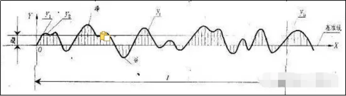
1, the contour arithmetic mean deviation Ra
Arithmetic average of the absolute value of the distance between the points and the baseline in the measured direction (Y) within the sampling length.
2, micro irregularities ten point height Rz
Refers to the sum of the average of the five maximum contour peak heights and the average of the five maximum contour valley depths within the sampling length.
3, the maximum height of the contour is Ry
The distance between the highest peak and the lowest bottom line within the sampling length.
At present, RA is mainly used in the general machinery manufacturing industry.
4, the roughness representation method
5. The influence of the roughness on the performance of the parts
The surface quality of the workpiece directly affects the physical, chemical and mechanical properties of the processed parts, and the working performance, reliability and life of the product largely depend on the surface quality of the main parts. Generally speaking, the surface quality requirements of important or key parts are higher than ordinary parts, because the parts of good surface quality will greatly improve their wear resistance, corrosion resistance and fatigue damage resistance.
6. Cut liquid
① The role of the cutting fluid
Cooling effect: cutting heat energy takes away a lot of cutting heat, improve heat dissipation conditions, reduce the temperature of the tool and workpiece, so as to extend the service life of the tool, can prevent the workpiece caused by thermal deformation size error.
Lubrication: cutting fluid can penetrate between the workpiece and the tool, make the small gap between the chip and the tool form a thin adsorption film, reduce the friction coefficient, so can reduce the friction between the cutting force and cutting heat, reduce the wear of the tool and can improve the surface quality of the workpiece, especially for finishing, lubrication is important.
Cleaning: the small chips generated in the cleaning process are easy to adhere to the workpiece and tools, especially when drilling deep holes and twisted holes, the chips are easy to block in the chip groove, affecting the surface roughness of the workpiece and the service life of the tool. The use of cutting fluid can quickly wash away the chips, is the cutting smoothly.
② There are two kinds of common cutting fluids
Emulsion: mainly play a cooling role, emulsion is the emulsified oil with 15~20 times of water dilution, this kind of cutting liquid specific heat, small viscosity, good fluidity, can absorb a lot of heat, the use of this kind of cutting liquid is mainly to cool the tools and workpieces, improve the tool life, reduce heat deformation. The emulsion contains more water and has poor lubrication and rust prevention function.
Cutting oil: the main component of cutting oil is mineral oil, this kind of cutting fluid has small specific heat, large viscosity, poor fluidity, mainly plays a lubrication role, commonly used is mineral oil with low viscosity, such as oil, light diesel oil, kerosene, etc.