Hot Keywords:
- All
- Product Name
- Product Keyword
- Product Model
- Product Summary
- Product Description
- Multi Field Search
Views: 1 Author: Site Editor Publish Time: 2025-04-23 Origin: Site
As the most common way of mechanical connection, interference fit is widely used in high load parts such as shaft and hub, bearing inner ring and shaft, gear installation, train wheel pressing and so on. It forms a tight fit through the interference between parts to achieve reliable torque or axial force transmission.
However, stress control during installation is always a difficult point in design and process: different assembly methods will lead to different degrees of stress concentration, residual deformation and even crack risk. Therefore, reasonable control of interference, tolerance grade and assembly method is the key to achieve high quality connection.
What is an interference fit?
The overfitting is the interference between the assembled parts in the forward direction (that is, the inner hole size of the outer part is smaller than the outer diameter of the inner part before assembly), which requires the use of external force to press or temperature difference assembly.
Common coordination levels include:
H7/p6, H7/r6: medium interference, used for gears, bearing seats, etc
H7/s6, H7/u6: large interference, used for wheel and flywheel pressing

The installation method of interference fit
�� 1. Cold pressing (cold press fitting)
Suitable for small interference (0.01~0.05 mm)
It can be forced into place with the help of hydraulic or mechanical press
The assembly speed needs to be controlled accurately to avoid scratches on the interference surface
�� 2. Hot fitting/cold shrinking fit
The outer part is heated and the inner part is cooled to achieve size reversal
After installation, the temperature recovers and strong interference force is generated
It is often used for pressing large gears, wheels and shafts
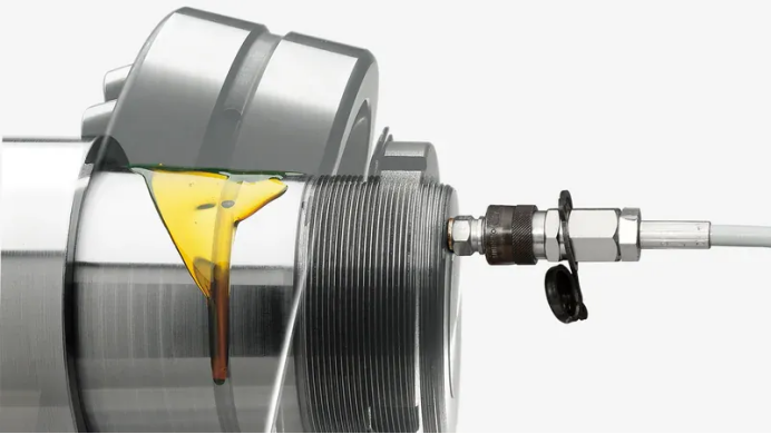
��3. Hydraulic assistance (hydraulic expansion)
The friction self-locking is destroyed instantly by high pressure oil film, and the assembly force is reduced
Suitable for high interference, heavy parts assembly
After the installation is complete, the oil pressure is released and contact is restored
Sources of stress during installation
Contact stress: the contact surface produces a great contact compressive stress due to excessive interference, which may cause local plasticity
Residual stress: there is an unrelieved reaction force between the inner and outer parts after assembly
Thermal stress: In hot fitting, uneven cooling is easy to lead to local cracks or loss of roundness
Assembly eccentricity: assembly misalignment, resulting in ellipticity deviation or surface indentation

How to reduce installation stress through tolerance control?
✅ 1. Preferably select the appropriate cooperation level
Different mating grades correspond to different interference ranges, and the maximum interference value should be calculated based on the elastic modulus of the material and the working temperature
Refer to ISO series recommended standards for selection (such as H7/p6, H7/r6)
✅ 2. Consider the effect of assembly temperature difference
The difference of thermal expansion coefficient of materials should be considered in hot assembly to avoid interference beyond the design range after cooling
For example, when the steel shaft is heated at 200℃, the linear expansion can reach 0.24mm/m, which should be used as the basis for tolerance correction
✅ 3. Reasonable design of chamfer and transition area
The chamfer guides assembly and reduces stress concentration at the start
Recommended chamfer at the shaft end 1 x 45 and hole opening 0.5 x 45

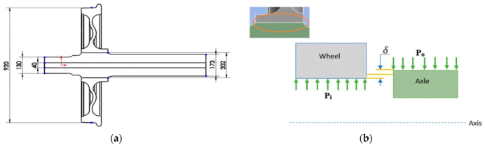
✅ 4. Use finite element analysis to simulate stress distribution
Perform 2D/3D contact analysis on key assemblies
The stress position and amplitude of the maximum contact area were determined, and the length-to-diameter ratio and material elasticity were optimized

Typical application cases and empirical data
The design of interference fit is not only the selection of a fitting code, but also the comprehensive balance of mechanics, thermodynamics and technology
In the initial design, the interference and stress level should be calculated according to the material properties, working temperature and assembly mode
The tighter the tolerance, the more difficult the assembly, and the more scientific assembly methods and residual stress control means should be matched
The ultimate goal is: strong coordination, safe installation, stable operation and easy maintenance